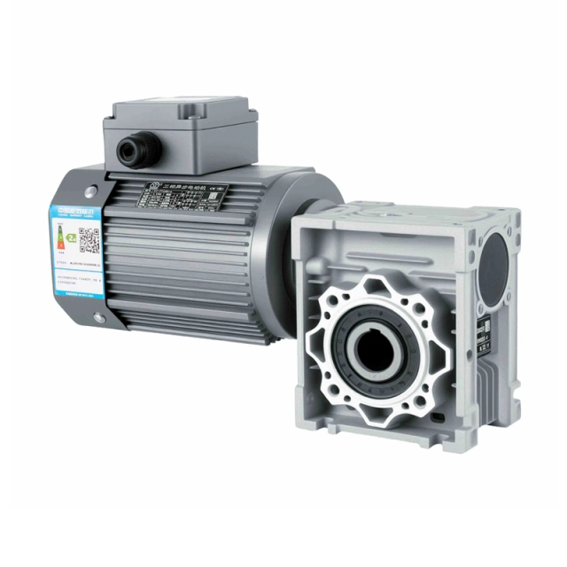
An oil pump motor is essentially a geared motor assembled from a gearbox and an electric motor. Its key function is to increase torque and reduce speed ratio. It is widely used in many factories, and speed reduction is generally achieved through a gearbox
Briefly describe the differences between DC motors and speed reducers.
An oil pump motor is essentially a geared motor assembled from a gearbox and an electric motor. Its key function is to increase torque and reduce speed ratio. It is widely used in many factories, and speed reduction is generally achieved through a gearbox.
A speed reducer is an integrated unit of a reducer and an electric motor. This type of integrated unit is also generally called a cycloidal motor or geared motor. It is usually assembled by professional reducer manufacturers and integrated with the electric motor as a single mechanical device. A speed reducer is a force transmission mechanism used in applications requiring high torque and not necessarily high-speed rotation. For example, in automated equipment. With the development of industrial production and the automation of factories, the demand for speed reducers is increasing. There are many ways to reduce speed, but the most common method is to use gears to reduce speed, which reduces space occupation and costs. Therefore, some people also call speed reducers gearboxes.
A pushrod motor is a rotary device that converts electromagnetic energy into mechanical energy. It primarily consists of a solenoid winding or distributed stator winding to generate an electromagnetic field, and a rotating synchronous motor or rotor. Current flows through its transmission lines, and the rotor rotates under the influence of the electromagnetic field. Some types of this device can be used as motors or generator sets. A speed-regulating motor is a device that converts DC power (45Hz or 60Hz) into AC power of various frequencies to achieve speed regulation. In this device, the control circuit controls the main power circuit, the inverter circuit converts AC current into DC power, the DC intermediate circuit smooths the output of the inverter circuit, and the motor then converts the DC power back into AC current. Variable frequency drives (VFDs) achieve speed regulation by changing the frequency of the motor's rotor winding power supply.